Description
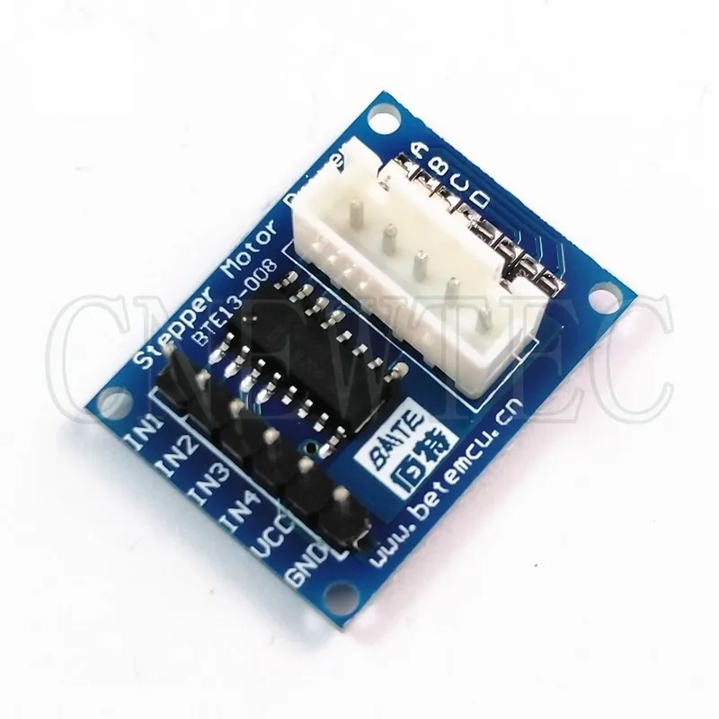
ULN2003 high power chip drives stepper motor
A, B, C, D LEDs indicate the status of the four-phase stepper motor when it is running
Equipped with a standard interface for stepping motor, which can be directly inserted when using.
Wiring method:
The IN1~IN4,VCC,GND on the left correspond to the 4 IO lines of the microcontroller;
The white socket pins on the right side are defined as A, B, C, D,VCC from top to bottom (connected to the stepper motor common line, A phase, B phase, C phase, D phase);
It can be used directly by plugging into the microcontroller development board or system board. It needs to lead out 4 IO ports, 5V and ground from the development board.
Development board/system board and motor driver board are connected by 6 dupont wires


Reviews
There are no reviews yet.